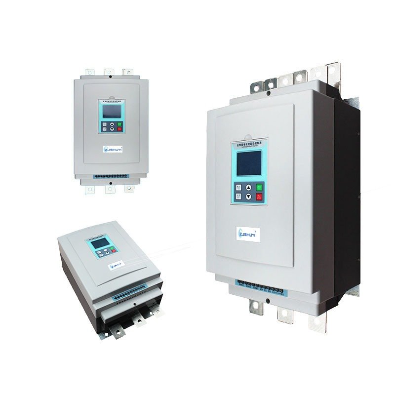
Zhejiang Shuyi Electric Co. Ltd
Mobile/WhatsApp: 008613355775769
Direct Tel/Fax:0086(577)62840011

Safe Circuit Integration of Soft Starters: A Step-by-Step Guide

Share This Post

Meta Description

Learn how to safely integrate soft starters into circuit systems, ensuring proper wiring, protection, and compliance with electrical standards for reliable motor control.

1. The Importance of Safe Soft Starter Circuit Integration

Soft starters are critical for protecting motor systems from electrical stress, but their effectiveness depends on proper circuit integration. Safely connecting a soft starter involves more than just physical installation—it requires matching electrical parameters, implementing protective measures, and adhering to industry standards. This guide outlines the key steps to ensure your soft starter operates safely and efficiently within any circuit system, minimizing risks of overloads, voltage fluctuations, and equipment damage.

2. Pre-Integration Circuit Compatibility Checks

Before wiring a soft starter, verify these critical compatibility factors:

  • Voltage & Current Ratings:
    • Ensure the soft starter’s input voltage (230V/480V/690V AC) and current capacity (10–1,000A) match the motor and power supply. A 55kW motor, for example, requires a starter rated for 110–130A to handle normal load variations.
  • Motor Type Compatibility:
    • Confirm compatibility with induction or synchronous motors, as some starters optimize for specific motor designs (e.g., constant-torque vs. variable-torque applications).
  • Environmental Conditions:
    • Check IP/NEMA ratings (e.g., IP54 for indoor use, IP66 for harsh environments) to ensure the starter’s enclosure protects against dust, moisture, or vibrations in the target circuit location.

3. Step-by-Step Wiring & Grounding Procedures

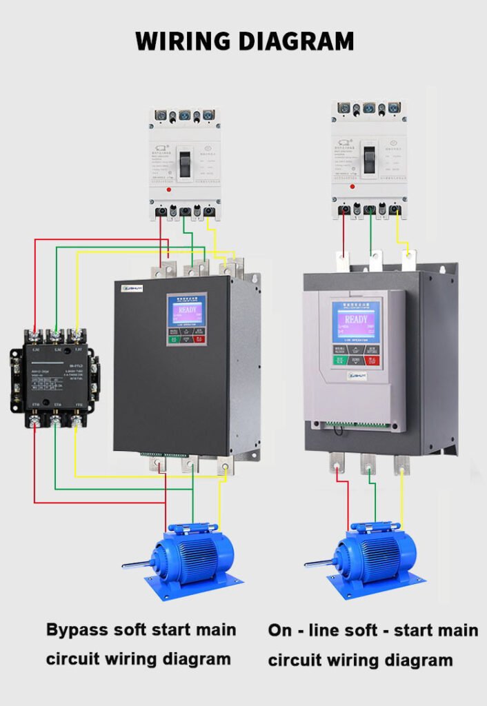
Proper wiring is essential for safe operation:

  1. Power Supply Connection:
    • Connect the input terminals (R, S, T) to the AC power source using appropriately sized cables (AWG 10–4 depending on current), ensuring tight connections to prevent arcing.
  2. Motor Termination:
    • Link the output terminals (U, V, W) to the motor windings, double-checking phase sequence to avoid reverse rotation that could damage the drivetrain.
  3. Grounding Requirements:
    • Install a dedicated grounding conductor (≥6mm²) between the starter’s grounding lug and the electrical panel’s grounding bus, reducing the risk of electric shock and EMI interference.
  4. Control Circuit Wiring:
    • Connect start/stop signals, fault relays, and communication cables (e.g., Modbus RTU) using shielded wires to minimize noise interference with control signals.

4. Installing Protective Devices for Circuit Safety

Integrate these components to safeguard the circuit:

  • Overcurrent Protection:
    • Install a circuit breaker or fuse (rated 1.5–2x the starter’s continuous current) upstream to protect against short circuits and overloads.
  • Surge Suppression:
    • Add metal-oxide varistors (MOVs) or TVS diodes at the input/output to absorb voltage spikes up to 6kV, preventing damage to the starter’s thyristor modules.
  • Thermal Overload Relays:
    • Configure electronic overload protection with trip characteristics compliant with IEC 60947-4-1, ensuring rapid shutdown during abnormal temperature increases.

5. Compliance with Electrical Standards & Best Practices

Adhere to these global standards for safe integration:

  • IEC 61800-3: Ensures electromagnetic compatibility (EMC) by installing line reactors or filters to limit harmonic distortion (<5% THD).
  • NFPA 70 (NEC): Requires proper wire sizing, grounding, and overcurrent protection for motor circuits in North America.
  • EN 60204-1: Specifies safety requirements for machine electrical systems, including emergency stop integration and fault diagnostics.
  • Best Practices:
    • Label all terminals and cables for easy maintenance.
    • Perform a pre-power test using a multimeter to confirm correct wiring and resistance values.
    • Commission the starter with a gradual voltage ramp to test motor response without mechanical stress.
VFD

6. Troubleshooting Common Integration Issues

Address these frequent challenges during installation:

  • Phase Loss Detection: If the starter trips due to phase imbalance, check wiring connections and verify the power supply’s voltage stability.
  • Overvoltage Faults: Install a line conditioner or review the starter’s voltage tolerance (±10% of rated voltage is typical).
  • Communication Errors: Ensure protocol settings (baud rate, parity) match the control system and use twisted-pair cables for data lines.

Conclusion

Safe circuit integration of soft starters is a critical step in optimizing motor performance while ensuring operator safety and equipment longevity. By prioritizing compatibility checks, following proper wiring procedures, and implementing robust protection measures, you can minimize risks and maximize the benefits of soft starter technology. Always refer to the manufacturer’s guidelines and local electrical codes to ensure compliance, and conduct regular maintenance to keep your circuit system operating at peak efficiency.

Contact Us

Tel/Fax: 0086-577-62840011

Wechat/WhatsApp: 00861586807525

Subscribe To Our Newsletter

Get updates and learn from the best

More To Explore

Do You Want To Boost Your Business?

drop us a line and keep in touch

Ask For A Quick Quote

Enter your request below and send it to us, and we’ll get back to you ASAP!

Ask For A Quick Quote

Enter your request below and send it to us, and we’ll get back to you ASAP!